2017年8月21日星期一

Milling machine differential dividing method

As the milling machine dividing disc with holes limited, some of the division number because there is no suitable hole ring, and can not be simple dividing method, such as 73, 83, 113 and so on. At this point the differential dividing method can be used.
Using differential dividing, should loosen locking screws, the dividing plate can be driven bevel gear rotary milling machine, and the dividing spindle taper hole arranged in the back-end transmission shaft, the change gear of a, b, c, d and Axis II connection (Figure).
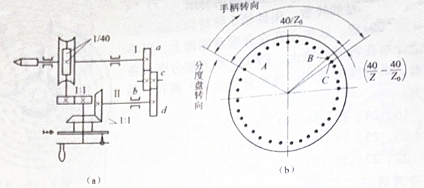
Differential working principle is as follows: Set the workpiece requirements for the degree of Z, and Z> 40, then the indexing spindle should be transferred to each 1 / Z turn. At this time, the handle should still turn 40 / Z turn, that is, the pin should be transferred from point A to point C. With the C point positioning, but the dividing plate at the C there is no corresponding hole for the identification of the location, and thus can not be used to achieve a small degree of sub-indexing. In order to use the milling machine on the dial circle, select Z0 to calculate the number of revolutions of the handle, the handle turns 40 / Z0 turn, that is, the switch from A to B, with B point positioning. At this time if the dividing disc is fixed, the handle turns 40 / Z0 instead of the required 40 / Z turn, there is a difference between the two. To compensate for this difference, turn the hole at point B to point C for pin positioning. To this end, the gears can be used to connect the milling machine to the dividing head spindle and the dividing plate. During the dividing process, when the latch is moved from point A to point C, the dividing plate is rotated by a number equal to the difference making the hole is just aligned with the latch.
Motion balance:

Simplification has to replace the formula:
In order to facilitate the use of replacement gear Z0 should be selected close to Z (can be greater than or less than Z) and 40 with a common factor value.
When Z0> Z is selected, the direction of rotation of the handle and the dial should be the same, and the gear ratio is positive.
When Z0 <Z is selected, the direction of rotation of the handle and the dial should be reversed, and the gear ratio is negative.
FW125 type milling machine dividing head with a module with a gear number of 1.75mm or less:24(two),28,32,40,44,48,56,64,72,80,84,96,100, A total of 15.

2017年8月20日星期日

Milling Machine Simple Dividing Method

When the number of divisions is large, you can use a simple dividing method of milling machine. Before the dividing, engage the worm and the worm gear, fix the dividing plate 7 with the locking screw 9 so that it can not be rotated and adjust the latch J to align it with the hole of the selected dividing plate.
When dividing, pull out the latch J, turn the handle K, drive the dividing the head spindle to the desired dividing position, and then reinsert the plug into the dividing hole.
Set the workpiece to be equal to the score Z, that is, each time the division of the head of the spindle should be turned 1 / Z turn. By the transmission system can be seen, the handle each time the degree of rotation should be:
The above formula can be written as follow
(q is the number of holes in the selected hole; p is the number of holes that the pin 10 should turn over the hole of the q hole.)
Example: In the FW125 milling machine division head on the dividing, the degree of division Z = 32;
solution:
The fraction in the upper form is simplified into the simplest integer, which is 1 / 4, and then the numerator and denominator are multiplied by the same integer, so that the denominator is the number of holes in the hole, 16 or 24, 36, etc. on the dial.In this case, the dividing handle should be turned one full turn, then turn the 4 hole spacing between the 16 holes, or turn the 6 holes apart on the 24 hole.
To ensure that the dividing is correct, the angle of the dividing fork 5 should be adjusted so that its inner edge contains (p + 1) holes in the holes of the q holes so that the identification pin 10 should be turned the hole spacing, to prevent the operation of the error. The above is the simple dividing method of milling machine.

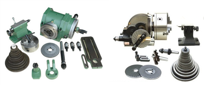
Milling machine dividing head

In the use of milling machine for processing, we often encounter milling hexagonal, gear, spline and engraved line and so on. At this time, the workpiece after each milling or - slot, you need to turn an angle, and then milling the second side, the second slot and so on. This work is called dividing. Dividing head is based on processing needs, the workpiece in the horizontal, vertical and tilt the location of the organization. One of the most common is the universal dividing head.
1. The use of the universal dividing head
Lift table milling machine is equipped with a variety of accessories, used to expand the scope of technology, including universal dividing head is a commonly used accessories. The machined workpieces are mounted on the top or chuck of the universal dividing head spindle and can be operated as follows:
①the workpiece around the axis of a certain degree of rotation to complete the equal or unequal circle indexing work. Such as processing square head, hexagonal head, gear, sprocket and unequal knife reamer and so on.
②through the replacement gear, by the dividing head drive the workpiece continuous rotation, and milling machine table with the vertical feed movement, can be processed spiral groove, helical gear and Archimedes spiral cam.
③holding the workpiece with a chuck, so that the workpiece axis relative to the milling machine table tilted a required angle, for processing and the workpiece axis intersect a certain angle of the groove or plane.
2.The construction of the universal dividing head
The following to FW125 universal dividing head as an example, indicating the structure and adjustment method of the milling machine dividing head. In the figure, the dividing head spindle 2 is mounted in the drum-shaped casing 4, which is supported on both sides by a journal on both sides and rotatable about its axis so that the spindle is adjusted to a desired angle within a range of 95°above the horizontal line The The front end of the dividing head has a taper hole for the installation of the top 1, with a bit of a pyramid on the outside for the installation of a three-jaw chuck.
Turn the dividing handle K, the transmission ratio u = 1/40 worm gear pair, driven by the dividing head spindle to the desired dividing position.The number of revolutions of the dividing handle K at the indexing is determined by the number of holes in the perforations of the dividing plate 7 by the latch J. These holes are distributed on the concentric circles with equal number of holes on the end of the dividing disc. FW125 universal dividing head with three sub-dial, for the selection of sub-degree, each sub-plate has 8 holes, the number of holes per hole were:
    the first     16、24、30、36、41、47、57、59
    the second  23、25、28、33、39、43、51、61
    the third    22、27、29、31、37、49、53、63

2017年8月18日星期五

Milling machine table horizontal and vertical feed control mechanism

The horizontal and vertical feed control mechanism of the X6132 milling machine table is shown in the figure. Handle 1 has upper, lower, front, rear and middle five working positions. When the handle 1 is moved forward and backward, the drum is driven by the ball at the front of the handle to move left and right axially. When the handle 1 is moved up and down, the drum 9 is rotated back and forth within a certain range by the flat groove on the hub body 3, the flat key 2 and the shaft 4.

On the circumference of the drum 9, the grooves with bevels control the micro switches SQ3, SQ4, SQ7 and SQ8, respectively. Where SQ8 is used to control the opening or disconnection of the electromagnetic clutch M5, which is used to turn on or off the electromagnetic clutch M4, i.e., to turn on or off the vertical feed motion and the lateral feed motion, respectively. SQ3, SQ4 is used to control the forward and reverse rotation of the feed motor, so that the milling machine table is moved forward, down and backward.
When the handle 1 is pulled forward, the drum 9 is moved axially to the left, and the bevel on the drum presses the lower pin 7 and acts on the microswitch SQ3 to turn the feed motor forward. At the same time, the pin 5 on the drum circumference, acting on the microswitch SQ7, so that the lateral feed electromagnetic clutch M4 through the power to work, so as to achieve the milling machine table forward horizontal feed movement.
When the handle 1 is pulled back, the drum 9 is moved axially to the right, the bevel on the drum presses the lower pin 8, acts on the microswitch SQ4, reverses the feed motor; the pin 5 is still in the drum round on the circle, so that the electromagnetic clutch M4 through the work of compact, to achieve the back of the table horizontal feed movement.


When the handle 1 is moved to the upper position, the drum 9 is rotated in the counterclockwise direction, and the inclined surface thereon is pressed against the pin 8 to act on the microswitch SQ4 to reverse the feed motor; the pin 6 is on the drum circumference , the lower pin 6 is pressed and acted on the microswitch SQ8 so that the electromagnetic clutch M3 is energized and pressed to achieve the upward movement of the milling machine table.
When the handle 1 is pulled down, the drum 9 is rotated in the clockwise direction, and the inclined surface thereon is pressed against the pin 7 to act on the microswitch SQ3 so that the feed motor is rotated forward; the pin 6 on the drum circumference is pressed, so that the micro-switch SQ8 work, so that the electromagnetic clutch M3 power on the work, to achieve the milling machine table down the feed movement.
When the handle 1 is pulled to the middle position, the top pins 8 and 7 are in the groove of the drum, the freckers SQ4 and SQ3 are released, the feed motor stops rotating, and the pins 5 and 6 are also in the drum slot, release the micro switch SQ7, SQ8, so that the electromagnetic clutch M4 and M3 power off, so the milling machine table front and rear feed movement and the upper and lower feed all stop.

2017年8月17日星期四

Milling machine table longitudinal control mechanism

The longitudinal feed control mechanism of the X6132 milling machine table is shown in the figure.

The longitudinal feed movement of the table is controlled by the handle 23, and the microswitch SQ1 or SQ2 is pressed while the end face clutch M5 is turned on or off, so that the feed motor is rotated forward or backward to effect operation the vertical or leftward longitudinal movement of the table. The shaft 6 is provided with a spring 7 and a fork 5 for urging the clutch M5, and the force of the spring 7 causes the shaft 6 to move leftward to drive the fork 5 to the left by the clutch M5; the longitudinal feed movement of the table , But also by the other side of the milling machine to manipulate the handle, pull the handle, the lever, pendulum on the pin 10, the lower end of the fork 9 so that the bump 2, the next swing.

When the handle 23 is pulled to the left, the pressing block 16 is swung to the left, the microswitch 22 (SQ2) is pressed, and the fork 14 is rotated clockwise while the feed motor is rotated in the opposite direction. The sleeve 2 is pivoted clockwise by means of a screw and the swing block 11 so that the projection 2 also oscillates clockwise and the highest point of the projection 2 leaves the left end face of the shaft 6, Under the action of the spring 7, the shaft 6 is moved leftward to drive the fork 5 to the left and the clutch M5 is turned on to realize the longitudinal feed movement of the milling machine table to the left.
When the handle 23 is pulled from the left to the neutral position, the presser 16 loosens the jog switch 22 (SQ2) and the feed motor stops rotating; and the projection 2 oscillates counterclockwise and its highest point pushes the shaft 6 to the right , The clutch M5 is disengaged by the fork 5, and the longitudinal feed movement to the left is stopped.
Similarly, when the handle 23 is pulled from the left to the right position, the pressing block 16 presses the microswitch 17 (SQ1), and the feed motor rotates forward. At the same time, since the projection 2 is swung counterclockwise, the highest point is left The left end face of the shaft 6 is turned on again by the spring 7 clutch M5, thereby effecting the milling machine table to the right longitudinal feed movement.

2017年8月4日星期五

Milling Machine Table

First of all, let's look at the structure of milling machine table. The vertical feeding and rapid movement of the worktable of the lifting table milling machine are usually driven by screw and nut pairs.
The table structure of the X6132 milling machine is shown in figure. It is composed of the worktable 7, the bed saddle 1 and the rotating disk 3.
The bed saddle 1 uses its rectangular guide to engage the rails of the lift to move the table horizontally on the platform rail. When the table is not moved horizontally, the saddle can be clamped to the lifting table by the action of the eccentric shaft 12 by the handle 13. The table 7 can be moved longitudinally along the dovetail rail above the rotating disk 3. The milling machine table, together with the turntable, can be rotated about -45 °to 45 °about the axis Ⅷ of the bevel gear and fastened to the saddle using bolts 14 and two arc press plates 2.
The longitudinal feed screw 4 is supported on the sliding bearing at the left front bracket 6 of the table and the thrust ball bearing and the tapered roller bearing at the right rear rear bracket 10 of the table to bear the radial force and the axial force in both directions.The clearance of the bearing is adjusted by nut 11. The handwheel 5 is sleeved on the lead screw 4, and when the handwheel 5 is pushed inward and the compression spring is applied to the end face clutch M, the manual milling machine table can be moved longitudinally. On the rotary disc 3, the clutch M5 is splined with the spline sleeve 9 and the spline sleeve 9 is connected to the longitudinal feed screw 4 having the keyway by the slide key 8, so that the end face tooth clutch M5 is turned on to the left, the movement from the shaft XVIII is driven by the bevel gear pair, M5 and the slider 8 to drive the longitudinal feed screw 4 to rotate. Since the double nut is fixedly mounted on the left end of the turntable, it can neither rotate nor move axially. Therefore, when the longitudinal feed screw 4 is subjected to the rotary movement, it is moved axially at the same time, so that the table 7 is moved in the longitudinal direction or moved rapidly.
Through the above description, I believe you have a clearer understanding of the structure of the milling machine table.

2017年8月3日星期四

Milling Machine Speed Change Mechanism

The main movement and feed movement of X6132 milling machine are controlled by the hole plate speed change control mechanism. The following we take the main speed control mechanism as an example to explain its working principle.
As shown in the figure is the use of hole plate speed control mechanism control triple slip gear schematic. Milling machine hole plate speed control mechanism mainly by the hole plate 4, the rack shaft 2 and 2 ', gear 3 and fork 1 composition.
The hole plate 4 is divided into several groups with different diameters, and each circumference is divided into 18 equal parts. According to the requirements of the gears at different positions during the gear change, the 18 positions are divided into three states: drilling big hole, drilling small hole or no drilling. The rack shafts 2 and 2'are machined with two rows of shoulder diameters of D and d respectively. The shoulder diameter of the d can pass through the holes on the orifice, and the shoulder diameter of D can pass through the big holes on the hole plate. Speed change, the first plate to the right shift, so that it back off the rack axis, and then according to the requirements of speed change, turn the disc to a certain angle, then make the hole plate left shift reset. When the hole plate is reset, the sliding gear can obtain three different positions through the big holes, the small holes or the non holes of the hole plate, so as to achieve the purpose of the speed change of the milling machine.Three working states are:
①The position of the corresponding rack shaft 2 on the hole plate is without hole, and the position corresponding to the rack shaft 2'is a big hole, and when the hole plate is reset, the left and top rack shaft 2 is pushed, and the triple sliding gear is pushed to the left position by the shifting fork. The rack shaft 2'moves right under the combined action of the rack shaft 2 and the pinion 3, and the shoulder D passes through the large hole on the hole plate;②The two holes are small holes, the small shoulder D of the rack shaft passes through the small holes on the hole plate, and the two rack shafts are in the middle position, so that the sliding gear is in the middle position by shifting the fork;③The hole plate corresponding to the rack shaft
2 position for large holes corresponding to the rack shaft 2'position without holes, the hole plate top rack shaft 2' left, and 3 to 2 through the gear rack shaft shoulder through hole right, and the gear is in the right place.
The structure of the main control mechanism is shown in the figure. It is an independent component mounted on the left side of the bed column of the milling machine and is operated by the handle 1 and the speed plate 10 for variable speed operation.When changing the rotational speed,the handle 1 is pulled out, the handle 1 by a pin 2 for rotation center, disengaged from the positioning pin 3 on the handle groove position; then counterclockwise rotation of the handle 1 is about 250 degrees, the steering wheel 9, and the flat key gear sleeve 4 to rotate, and then by the mobile rack gear 5 makes axis 11 to the right, the fork 12 shifts 8 hole plate moves to the right, the hole plate 8 from each rack shaft, to prepare for the 8 hole plate translocation; rotating speed of disc 10 to the desired speed position by a pair of bevel gears to 8 hole disc turns corresponding angle; finally, the handle 1 push back to the original position and re positioning, then move to the left and 8 hole disc drive each rack shaft for the corresponding displacement, speed of transformation.When changing speed, in order to make the sliding gear meshing position change in easy meshing, milling machine is provided with a main motor instantaneous impulse device, it uses bump 6 of gear 5 press the micro switch 7 is switched on, with the main motor power, the main motor to achieve a momentary impulse, drive the transmission gear of the main gear box to rotate at a slow speed, sliding gear can be smoothly moved to another position of engagement work.
The above is the introduction of the milling machine speed mechanism.