2017年12月24日星期日

Spindle taper, you should know when choosing a universal milling machine!

When choosing a universal milling machine, three of the most important machine parameters must be carefully confirmed, including the spindle taper, the worktable size and the worktable travel. Because these three parameters directly determine whether the milling machine you buy can meet the needs of your use. But for the parameters of the spindle taper, many people, especially those who have just entered the machine tool industry, will feel more strange. Now let's just analyze it.
First of all we have to understand what is taper. By definition, taper refers to the ratio of the diameter of the underside of the cone to the height of the cone; in the case of a truncated cone, the ratio of the diameter difference of the upper and lower circles to the height of the truncated cone.
People who are engaged in machine tool industry often talk about NT40, R8, ISO40, ISO50 and other words when talking about machine tools. Yes, these are the taper of the spindle of a machine tool. There are so many different expressions, because the taper standards used by different machine tools are different, so the way of naming is different. In practice, there are many kinds of specifications for machine tool taper, and specifications are varied. Here we cannot elaborate one by one. If interested, you can access a standard data. Now let's talk about common taper standards.
The common taper of all kinds of machine tool products: Morse taper (MT), R8, ISO (7:24), BT30, BT40, BT50 and so on. The taper of the machine tool under a specific standard is determined mainly according to the function and performance of the machine tool.
The Morse taper was invented in nineteenth Century by an American mechanic Stephen A. Morse to solve the problem of the clamping of the twist drill. It was later popularized as a American Standard and gradually developed into one of the global standards. The taper has seven models with 0, 1, 2, 3, 4, 5, 6. The taper value has a certain change. The taper is also divided into a long cone and a short cone. The long cone is used in the spindle hole of the active machine tool, and the short cone is used for the machine tool accessories. The taper is mainly used in drilling machine and lathe. Because of the long length of the taper and the good orientation of the axis, it is very suitable for the use of bore holes and reaming holes.
ISO (7:24) is an international standard. Although the guide length is shorter, but the taper hole area is large, very suitable for milling. So it is widely used in milling machines, such as universal milling machine, vertical milling machine and so on. When buying universal milling machines, usually according to the power of the milling machine to choose a different cone, such as ISO30, ISO40, ISO50 milling machine. Small power milling machines need to be equipped with smaller tapered bore, while larger power milling machines are equipped with larger tapered bore.
BT is a Japanese standard, with a taper at 7:24. BT40 and BT50 are mostly used on CNC machine tools. Because the CNC machine tool products need to achieve automatic tool change, so the spindle taper is required to be accurate and easier to fall off when the knife is changed. The BT taper can be considered to be produced by removing the tail on the basis of the ISO taper. It is more convenient and quicker when changing the knife.
When the metal processing universal milling machine is finished, the taper of the spindle can not be changed easily. Therefore, only to determine the use of demand, and then use the demand to determine the need for milling spindle taper, as an important reference to buy milling machine, which is the right approach.

2017年12月21日星期四

Christmas is coming!

DXMC send the best wishes to all the customers and partners. Merry Christmas!
We are doing a Christmas sales promotion. Friends who are planning to buy 
universal milling machines and milling machine equipment in the near future do not miss it! https://www.cndxmc.com/

2017年12月15日星期五

5 tips for purchasing universal milling machines!

Many users do not know how to choose the universal milling machine they need correctly. Today we will talk about how to choose to the suitable milling machine. Before choosing, the following factors need to be considered:
1. Uses and functions
2. Using field
3. Budget
4 .Production
5. Development
Let's analyze these factors one by one.
1. Uses and functions
There are many types of milling machines, such as vertical milling machine, horizontal milling machine, bed type milling machine, profiling milling machine, universal milling machine, drilling and milling machine, CNC milling machine, gantry milling machine, etc.. Different milling machines have different uses.
For example, a metal processing vertical milling machine is suitable for machining flat, keyway, dovetail groove, bevel and some irregular workpieces, because its spindle is perpendicular to the worktable. Vertical mill machine is widely used in manufacturing factories, mines, workpiece processing and other fields.
Horizontal milling machine is also suitable for factories and professional businesses. Its spindle is horizontal, suitable for machining the side of the workpiece, as well as the use of horizontal milling cutter milling straight slot.
Profiling milling machines are designed primarily for the complex workpiece and special-shaped workpiece, so they can work on workpieces that can not be machined by conventional milling machines. These machines are usually based on the workpiece to be selected.
Universal milling machines usually have vertical milling and horizontal milling two functions, and universal milling head can rotate 360°. It can be suitable for a variety of processing occasions, more flexible and convenient.
2. Using field
Some clients use limited space for machines. In selecting the milling machine, whether the size of the machine and the future maintenance is convenient should also be considered. If the workshop is very small, or in the ship, family basement and other places to use, it will bring some trouble to the installation, use and debugging. When the machine tool is used normally, the space occupation is small, but the space needed for installation and maintenance is very large. Therefore, the customer must communicate with the universal milling machine tool manufacturer, and more consultation before purchase.
3. Budget
Budget is also considered when purchasing equipment. Some enterprises will consider buying some high-end machine tools because of sufficient funds. And some companies with insufficient budget can choose some medium and low grade machine tools according to their own product requirements, and the quality of machine tools produced by these small and medium-sized manufacturers can meet the needs. The management cost of large enterprises is three to five times that of small and micro enterprises. The management cost of small and medium-sized manufacturers is not high, so the machine will be more cost-effective than some large enterprises.
4. Production
Product output is a very important factor to consider when selecting machine tools. If you need to process a large amount of workpiece, you must choose a higher degree of automation, good quality mill machine. In addition, whether the after-sales service is perfect also need to consider.
Although the milling machine with higher automation degree has higher price, it is three to five times more efficient than ordinary machine tools in use. Because of the high output, the equipment will be used for a long time. Ordinary machine tools can be used continuously for 16 hours, and some high-quality equipment can be used continuously for 20 hours or even 24 hours.
5. Development
Short term use and long term use are often considered when purchasing machine equipment. Some enterprises only purchase equipment for a batch of orders, and they will sell machines after processing. In this case, special machine tools and single function machine tools are usually chosen. If there is a long-term use plan, it is necessary to consider the stability of the equipment and the comprehensiveness of the function.
Through the comprehensive evaluation of the above points, DXMC believes that it can provide you with a lot of valuable reference to purchase universal milling machine equipment, so that your procurement can be more reasonable, more economical and more effective.

2017年11月1日星期三

Equipment management of CNC universal milling machine

Equipment management of CNC universal milling machine is a systematic project, and should be based on the company’s production development and business objectives, through a series of technical, economic, organizational measures and scientific methods to carry out. In the specific use of equipment management, depending on the enterprise to buy and use CNC universal milling machine, select the following stages.
①In the early use of CNC universal milling machine, there is no mature management methods and the use of equipment experience, programming, operation and maintenance personnel are more unfamiliar. In this case, the CNC universal milling machine is generally placed under the production workshop management, focusing on training several technical staff to learn manual programming, automatic programming and maintenance techniques, and then teach the operator, and for a long time to allow technicians and operate workers as top class operation. Select the typical key parts of the enterprise, the preparation process, select the tool, determine the fixture and preparation procedures and other technical preparations.
②In the grasp of a certain application of technology and a certain number of  milling machines, these devices can be used professional management, centralized use of the method. Process technology preparation by the process sector is responsible for the production management by the factory unified balance and scheduling, CNC equipment concentrated in the CNC workshop.
③CNC machine tools and the number of more types of auxiliary facilities are relatively complete, relatively mature application technology, programming, operation and maintenance of the technical team is relatively strong, can be equipped with CNC machine tools in the appropriate general machine, the CNC workshop expanded into closed independent workshop, with the ability to independently produce a complete product. If necessary, equipment and tools can be achieved computer management, universal milling machine to start a higher rate of technical and economic benefits are better.
Whichever stage is used, equipment management must establish rules and regulations. Such as the establishment of fixed, fixed machine, fixed post system, job training, prohibition of undocumented operation. According to the characteristics of the equipment, the development of the operation and maintenance of safety procedures. In the equipment maintenance, to strictly enforce the record, that is, for each maintenance are doing the relevant records. The fault repair to do a good job on the fault records and instructions, and equipment maintenance and repair for all kinds of commonly used spare parts. Do the equipment technical information on the lend, custody, registration work.

2017年10月29日星期日

Milling machine CNC system hardware

From the hardware point of view, milling machine CNC system is divided into single microprocessor numerical control system and multi microprocessor numerical control system.
1. Single microprocessor numerical control system
In a single microprocessor numerical control system, the whole system has only one CPU, it uses centralized control, time-sharing way to control. Single microprocessor numerical control system of the main features of the performance: CPU time-sharing control. CPU through the address, data and control of the three major bus connected to the control unit and the exchange of information.
2. Multi-microprocessor numerical control system
Multi-microcomputer numerical control system will control the task is divided into various modules, each module by a separate microprocessor to control. The system through the coordination of the various modules to complete the control of the milling machine. Compared with the single microprocessor numerical control system, the operation speed of the multi-microprocessor numerical control system has been greatly improved.
Multi-microprocessor functional modules include:
1) management module. Used to manage and organize the entire milling machine CNC system work.
2) interpolation module. Mainly to complete the pre-processing before interpolation.
3) position control module. Used to compare the position setpoint with the actual value of the position, and adjust the output speed command to drive the milling machine feed motor.
4) memory module. The memory module is the main memory of the program and data, or the shared memory for data transfer between the functional modules.
5) PLC function module. It is part of the program in the switch function and the milling machine to the logic of the signal processing, to achieve the machine electrical equipment switching control.
6) operation panel and display module. This module includes part program, parameters and data, various operation commands input/output and display the various interface circuits required.
In the CNC system of multi microprocessor, the communication and communication between modules are mainly composed of shared bus and shared memory, two kinds of structure. In the shared bus architecture, each function module is plugged into a chassis with a bus socket, and the modules are effectively connected together by the milling machine system bus. In the shared memory architecture, each module exchanges information with the common memory, and the public memory is directly attached to the system bus, and each module can access the information.

2017年10月27日星期五

Milling machine CNC system

As the computer system of CNC milling machine, CNC system is very important to control the whole machining process of machine tools. In short, the role of numerical control system is: the input of the processing program after a series of data processing, the output of the control signal to the milling machine to complete the implementation of the processing procedures specified by the action, including the spindle movement, feed movement and auxiliary Features. In addition, the CNC system can also be connected with the computer or network, the implementation of data transmission and communication.
The CNC machining program contains information such as spindle S command, track command G00, G01, G02, G03, coordinate value command X, Y, Z, speed command F, auxiliary function command M. CNC system needs to carry out data processing of these information, and output the control signal.
After the machining program is input to the CNC system, the milling machine CNC system must decode the processing program and generate the data format which the numerical control system can recognize. The decoding result is stored in the specified register, such as the M code register, the G code register, the X, Y, Z registers, etc., for later data processing.
One way to decode is to translate the entire program once before the formal processing and to parse the program during the decoding process. Another way is to decode during processing, that is, the milling machine CNC system in the implementation of the current process block processing, the use of idle time on the subsequent program to decode and follow-up data processing, this approach is also known as preread processing. The more readable blocks, the more data processing functions of CNC systems.
The above is a brief introduction to the milling machine CNC system. In the next article, we will be from several aspects to carry out a more detailed description.

2017年10月26日星期四

CNC milling machine rotary transformer

The rotary transformer is a precision sensor that uses the electromagnetic induction principle to measure the angle, and is widely used in CNC milling machine. Rotary transformers are made of fixed, rotor core and windings, durable, unlike the encoder in the photoelectric encoder vulnerable to shock or vibration damage, suitable for use in harsh environments. Milling machine servo motor in addition to optional optoelectronic encoder, but also optional rotary transformer, as shown.
The milling machine revolving transformer is actually a special two-phase motor. There are two orthogonal decomposition of winding stator windings, and the excitation voltage, when the rotor rotates, and the relative position of the rotor windings changes, the decomposition of the rotor winding of the induction voltage into a functional relationship with the rotor angle. 
The induced voltage varies with the rotation angle of the rotor, and the induced voltage can be detected to detect the rotor rotation angle. In order to lead the rotor coil on the induced voltage, the actual use of the rotary transformer consists of two parts: a part of the decomposition device, composed of stator and rotor, the other part of the transformer. The primary winding of the transformer and the rotor winding of the resolver are fixed on the rotating shaft and rotate together with the rotor. The rotor winding lead wire in the resolver is connected to the primary winding of the transformer. The secondary winding of the transformer and the stator in the resolver are fixed to the housing, respectively. The stator winding of the resolver is applied with an excitation voltage, and the induced voltage of the rotor winding when the rotor rotates is fed by the primary winding of the transformer by the secondary winding of the transformer.
Above is the basic working principle of CNC milling machine rotary transformers, thank you for your attention.

2017年10月25日星期三

CNC milling machine grating (Part 2)

In the last article we understand the basic composition, classification and function of the CNC milling machine grating, and today we look at the measurement principle of the grating.
In the transmission type incremental grating, when the grating with the light source, lens and a photosensitive element together with respect to the scale and move around the grating, grating and grating ruler to indicate the fringe produced optical phenomena, as shown in the grating generated on the move and the bright and dark stripes, the stripes called moire fringe.
Every move of a milling machine indicator grating pitch, which produce a moire fringe. The photosensitive element receives the change of the light and the dark of the moire fringe, namely, an electrical signal is generated, and the detection circuit processes the electrical signal generated by the photosensor and outputs a pulse signal. Because the width of the moire fringe is much larger than the pitch, the moire fringe has the effect of enlarging the pitch. Counting the output pulse, is to accumulate the pitch, the cumulative result is measured linear displacement. If the grating pitch is 20pm and the count pulse is 1000, the measured distance is 20μm * 1000 = 20000μm = 20mm.
In addition, the direction of the moire fringe movement is related to the direction of movement of the indicating grating. When the indicating grating is moved to the right, the moire fringes move down; and vice versa. Through a group of photosensitive elements on the moire fringes to detect the direction of movement, the output of two phase difference of 90° electrical signals to distinguish.
The above is the introduction on the CNC milling machine grating measurement principle, thank you for your attention.

2017年10月20日星期五

CNC milling machine grating (Part 1)

Grating is a high-precision position sensor, widely used in CNC milling machine, which mainly involves long grating and round grating two types. Long grating for the milling machine table and other moving parts of the linear displacement measurement, also known as linear grating. Round gratings are commonly used for angular displacement measurements such as rotary tables. The picture shows the grating installation diagram.
The grating body is fixed on the milling machine bed, the scanning head is fixed on the work table, the scanning head moves together with the work table, and the straight line displacement amount of the work table is converted into electric signal by cable output.
The picture shows the appearance and the internal structure of the grating. Ruler grating (also known as the main ruler) fixed in the body fixed. The ruler grating is made of optical glass or stainless steel strip. The ruler grating is engraved with equidistant stripe, which is called the pitch ω. 
In addition, the ruler grating is also engraved with a set of zero mark fringes, and according to the law of equidistant arrangement, its purpose is to return to the reference point in the process, to the nearest zero mark, save back to the reference point of time. The indicator grating (also known as the secondary ruler) corresponding to the ruler grating is also engraved with equally spaced stripes. Indicator grating is fixed in the scanning head and moved together with the scanning head. According to the projection of the light, the grating has two kinds of transmission grating and reflection grating.
The above is on the CNC milling machine grating of the basic composition, classification and the role of a brief introduction, you are welcome to continue to pay attention.

2017年10月19日星期四

Milling Machine Absolute Photoelectric Encoder

Milling machine absolute photoelectric encoder structure and incremental encoder is similar to the code, LED, photosensitive components and signal detection circuit and so on. The detection signal is binary coded, and each code corresponds to an angular position. The picture shows the absolute measurement and binary coding.
The milling machine has a code track (also known as track). As shown in the code on the code from the inside to the outside there are 8 yards, the code on the road by the binary law engraved with light or opaque stripes. The side of the disc is the light source and the other side is a group of photosensitive elements. When "0" to a certain angle, and the corresponding channel of the photosensitive element by the light output is "1" level, from the light output is "0" level, which constitutes a set of binary code. The number of bits in the binary code is the number of code channels, and each set of binary codes corresponds to a single angle, as shown.
Binary code has two types of natural binary code and Gray code. Natural binary code, the measured angle changes every time, binary coding may occur in a number of "0" and "1" changes, prone to error code, low reliability. Gray code, the measured angle changes every time, only one binary code "0" and "1" changes, Gray code is conducive to reducing the wrong code, improve reliability.
Because the binary code is distributed within 360°, when the code from 0°to 360°, the code back to the initial value, can not tell the number of turns of the code wheel, so when the angular displacement measurement, to using multi-turn absolute encoder.
The position data of the absolute encoder is stored in the memory, held by an external lithium battery, and the data is not lost after power failure. So the configuration of the absolute encoder CNC milling machine once the reference point after the completion of the set, after each boot power after the need to return to the reference point of the operation.
The above is a simple introduction to the milling machine absolute photoelectric encoder, hoping to help you.

2017年10月18日星期三

Milling Machine Incremental Photoelectric Encoder

Incremental photoelectric encoder in milling machine is mainly composed of light source, code plate, light rail, photosensitive components and conversion circuits and other components, as shown.
The incremental photoelectric encoder is engraved with radially light-colored stripes with equal pitch, and the adjacent two stripe represent a resolution angle α. There is a fixed encoder in the encoder, light rail engraved with A, B two groups of light transmission stripes. When the disc is rotated with the rotating shaft, the light is transmitted to the photosensitive element through the light transmission strip on the disc and the light rail, and the photosensitive element outputs the electrical signals of A and B and the phase difference 90°electrical angle, as shown. A, B two signals used to determine the direction of rotation, if A ahead B 90°, then the encoder forward. If B is advanced by A 90°, then the encoder is reversed.
There is also a light transmission stripes on the inside of the code wheel. When the code wheel turns a turn, the corresponding photosensitive element of the stripe produces an electrical signal Z, called a zero mark pulse (also called a turn pulse).
Milling machine Incremental photoelectric encoder is characterized by the generation of a pulse signal corresponding to an angular displacement increment, the increment is the resolution angle. Counting the pulse is the accumulation of diagonal displacement increments, the cumulative result is the measured angular displacement. In addition, since the count pulse frequency is proportional to the encoder speed, the speed of the milling machine encoder can be obtained by measuring the counting pulse frequency.
When the incremental encoder is de-energized, the current position information is lost. Therefore, the CNC milling machine with the incremental encoder is operated back to the reference point after power-on. The reference point is determined by finding the zero sign signal to establish the measurement reference.
The above is a brief introduction to the CNC milling machine incremental encoder, and welcome to continue your attention.

2017年10月17日星期二

CNC milling machine encoder

In the process of processing, milling machine CNC system to real-time detection of the current table and other moving parts of the actual location and speed, and with the command position and speed to compare, to achieve position control and speed control to meet the accuracy of position and speed stability control requirement.
 In the same way, CNC system also carries on the speed detection and the position detection to the spindle, in order to carry on the speed and the position control to the spindle. Modern CNC milling machine commonly used position and speed detection device, such as encoder and grating.
The encoder is used for angular displacement measurement and speed measurement, either in the servo motor and spindle motor, or independently. The picture shows the application of the encoder in the numerical control machine tool.
The servo motor is connected to the ball screw through the coupling. Servo motor rotation, the servo motor built-in encoder real-time detection of the servo motor rotor angular displacement and speed, indirect measurement of linear displacement. If the screw pitch is t, the CNC system obtains the linear displacement x of the milling machine table according to the angular displacement θ detected by the encoder.

The spindle encoder and spindle are connected with a 1: 1 timing belt for real-time detection of spindle speed and angular displacement. In addition, the encoder installed in the milling machine spindle motor can directly measure the motor speed and rotor angle.

2017年10月16日星期一

Milling machine linear motor

Feed drive being composed of servo motor, ball screw and milling machine worktable, there are mechanical transmission error (such as backlash, screw pitch reducer and screw nut cumulative error) and the transmission stiffness is low, these factors will affect the accuracy of position. In addition, by the servo motor and transmission mechanism, the maximum speed and acceleration are also limited.
Feeding drive using milling machine linear motor, the elimination of the motor to the workbench between all the intermediate links, reducing the mechanical transmission error, transmission stiffness and positioning accuracy, fast response. At present, the linear motor is more and more used in high-speed, high-precision CNC milling machine. The picture shows the appearance and composition of the linear motor.
Linear motors are essentially AC servo motors, consisting of primary and secondary sides. On the secondary side of the linear motor, the permanent magnet is mounted alternately on the base plate. A three-phase winding is mounted on the primary side slider, which is connected to the milling machine table. The table is supported and guided by a linear rolling guide and maintains a certain air gap between the slider and the permanent magnet.
When the primary side of the three-phase AC power, the resulting air gap magnetic field along the line, the magnetic field known as the traveling wave magnetic field. The magnetic field of the secondary side permanent magnet interacts with the traveling wave magnetic field to generate electromagnetic thrust, and the primary side slider moves linearly under the action of electromagnetic force. The linear motor can be driven by a servo motor drive. The primary and secondary sides of the linear motor can be fitted with cooling components to cool and cool the linear motor. The picture shows the application of linear motor in CNC milling machine feed.

2017年10月15日星期日

Milling machine step driver

The function of the milling machine step driver is to process and enlarge the input control pulse signal, and output the pulse power to each phase winding of the stepping motor, as shown. Step driver involves pulse distribution and power amplification.
1.Pulse distribution
Pulse distribution is used to control the running mode of the stepper motor, and its function is to send a series of command pulse signals issued by the numerical control system according to the power phase sequence. The assigned pulse signal is used as the control signal of each phase winding. Taking the milling machine three-phase stepper motor as an example, the number of pulse signals CP controls the angle of the stepping motor rotation, and the stepping motor turns a step angle every time a CP pulse is input. The frequency of the pulse signal CP controls the rotational speed of the stepping motor. The direction of the signal is TTL level, when the TTL is high, the stepper motor is running, and vice versa. The pulse distributor (ring distribution integrated circuit) assigns the CP pulse signals to the stepping motors A, B, and C windings in sequence according to the direction signals.
2.Power amplification
Each phase winding of the milling machine stepper motor has a power switch, the distribution of the pulse power amplification, in order to obtain the drive current of each phase winding. Single-supply power amplifier at high frequencies due to the winding current to reach the specified value, resulting in stepping motor output torque is insufficient. Low-frequency winding current easily intermittent, resulting in stepper motor speed instability. In order to overcome the shortcomings of single-supply power amplification, stepper drive there are high and low voltage power supply drive, constant current chopper drive and subdivision drive, these drive devices can improve the smooth operation of the milling machine stepper motor to eliminate oscillation.

2017年10月12日星期四

Milling machine stepper motor(Part 2)

In the previous article, we talked about the composition of the milling machine stepper motor and its control ways. Today we look at what features it has.
1. Hold torque
The stepping motor remains energized, but the rotor does not move and has torque output. At this time, the torque is called the holding torque, also known as the maximum static torque. Holding torque is an important measure of the ability of the milling machine stepper motor to withstand external load disturbance.
2. Torque-frequency characteristics and acceleration / deceleration
The output torque of the stepper motor varies with the energization frequency, which is called the torque-frequency characteristic. As the picture shows.
As shown in the figure, fs is the starting frequency, also known as the sudden jump frequency, the corresponding torque for the starting torque Ts. At the time of starting, the starting torque is greater than the torque Tr at the time of continuous operation due to the presence of the acceleration torque. The starting frequency is much lower than the continuous operating frequency, the starting frequency is generally only a few hertz.
If the starting frequency is too large, the milling machine stepping motor output torque is not enough to overcome the starting torque, it will lead to stepper motor can not start, out of step or stall phenomenon. After the start of the stepping motor, the highest frequency with the continuous rise of the frequency of the energization frequency is called the running frequency fr, and its value is much larger than the starting frequency. If the stepper motor running frequency is too high, will lead to the output torque is not enough to overcome the load torque, it will be out of step or stall phenomenon, accompanied by howling.
Understand the milling machine stepper motor these characteristics, I hope to help you some.

2017年10月11日星期三

Milling machine stepper motor(Part 1)

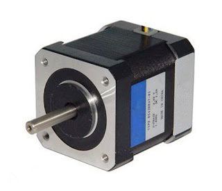
A stepper motor is a motor that converts a pulse signal into an angular displacement and is often used in the feed drive of an economical milling machine. As the stepper motor drive without speed and position detection and feedback, so the speed and position control accuracy by the stepper motor and feed the mechanical chain to ensure the accuracy.
1.Composition structure
Stepper motor stator consists of core and winding. The stator core is made of silicon steel sheet and is made into a pole shoe. Pole pieces of uniform surface of the tooth groove, pole with a winding coil, a pair of pole pieces to form a phase winding. The rotor has a reactive type and a mixed type. The reactive rotor core is made of silicon steel sheet, and the circumferential surface is arranged in the tooth groove. The hybrid rotor is equipped with permanent magnet in the rotor core. Stator per phase winding in accordance with the phase sequence after the pulse power generated stator magnetic field, the rotor under the stator magnetic field rotation. The picture shows the five-phase hybrid stepping motor structure diagram.
2. Control
(1) Step angle
Stepping motor each phase of the winding once every step, stepper motor rotor that is turned through an angle, the angle is called the step angle. The magnitude of the step angle determines the amount of linear displacement that the ball screw drives the milling machine table. For example, a milling machine stepper motor and ball screw through the coupling directly connected to the stepper motor step angle of 0.36°, screw pitch of 12mm, then each step angle corresponding to the table of the linear displacement of (12mm/360°) x 0.36°= 0.012mm. Therefore, the position control can be realized by controlling the number of energizing pulses. Stepping motor running process, the number of steps the rotor does not follow the pulse signal is called out of step, out of step will affect the position control accuracy.
(2) Speed and steering control
The speed and direction of the milling machine stepper motor are controlled by the frequency and phase sequence of the energized pulse power. Changing the frequency of the pulse power can change the speed, but the speed range is not wide, the maximum input frequency is generally not greater than 25kHz; change the phase sequence of the pulse power supply change the turn. There are two types of single-shot and double-shot, double-step angle is half of the single shot. The picture shows the three phase stepper motor power phase sequence diagram.

2017年10月10日星期二

Milling machine servo driver

AC servo driver is a common type of milling machine servo drivers. The servo motor needs to cooperate with the servo driver to complete the corresponding function.
1.AC servo motor vector control
AC servo motor frequency control is a self-control variable frequency synchronous motor system. The frequency and phase of the output current (voltage) of the frequency conversion device (servo drive) are controlled by the position of the rotor pole, which is a closed-loop control mode for stator frequency and phase of the stator winding. In the vector control process, the rotor magnetic pole position of the rotor pole axis of the U-phase stator winding axis angle θ, varies with the rotation of the rotor. The angle can be obtained by direct detection of the encoder or rotary transformer connected by the milling machine servo motor, as shown.
The AC servo drive is essentially a frequency converter for driving an AC servo motor. The AC servo drive controls the AC servo motor by the vector control strategy for the AC servo motor, as well as the SPWM and the inverter, as shown in the figure. Milling machine AC servo motor with vector control can get very good static and dynamic characteristics.
2. Control signal
AC servo drive control signals are analog and digital. The encoder in the servo motor feeds the speed detection signal to the milling machine servo drive on the one hand, carries on the speed control, and on the other hand, sends the position detection signal to the CNC system through the servo drive to carry on the position control. Simulation control, the wiring between the devices, the signal susceptible to interference, affecting the stability of the servo drive. With the development of digital bus control technology, the current milling machine CNC system and servo driver between the use of digital bus communication.

2017年10月9日星期一

Milling machine electromagnetic brake

The milling machine servo motor which drives the vertical ball screw is equipped with an electromagnetic brake, and the electromagnetic brake is an integral part of the servo motor. The structure is shown in figure.
When the ball screw is mounted vertically (such as the vertical axis of the milling machine or the Z axis of the machining center), the ball screw has no self-locking function. When the machine is powered off and there is no locking device, spindle box or turret will fall on their own. In order to prevent this phenomenon, the electromagnetic brake is mounted on the servo motor, and the motor rotor is locked by the electromagnetic brake when the servo motor is de-energized so that the screw can not be rotated.
In the electromagnetic brake, the brake disc is connected with the rotor shaft by splines, rotates with the rotor, and moves axially. When the servo motor is running normally, the brake coil is energized (+24V). The armature is overcome by the force of the electromagnetic force against the brake spring. The brake disc is released under the action of the return spring. The servo motor is in release state. When brake, the brake coil power loss, the armature in the brake spring under the action of rapid axial movement and push the brake disc, so that the brake disc pressed on the chassis, friction torque generated by the friction plate to lock the rotor shaft, so as to achieve the purpose of braking.
The above is about the milling machine electromagnetic brake introduction, if there are problems, welcome to discuss.

2017年10月8日星期日

CNC milling machine servo motor (Part 2)

In the last article, we introduced the development process of CNC milling machine servo motor and its composition structure. Today, let's talk about its working principle.
AC servo motor stator winding three-phase alternating current, the stator and rotor air gap generated between the rotating magnetic field, the rotor and the permanent magnet on the rotor magnetic field to attract each other, rotating the magnetic field to drive the rotor rotation, the rotor speed and rotating magnetic field speed consistent. Because the stator rotation magnetic field speed is proportional to the frequency of the power supply, so in the rated torque range, no matter how the load changes, as long as the power frequency unchanged, the motor speed remains unchanged, and the rotor speed is proportional to the power frequency.
In addition, the milling machine AC servo motor with a start, stop responding fast, wide speed range, overload capacity and so on. AC servo motor according to the speed, output torque, inertia and accuracy indicators such as series of products, such as FANUC AC servo motor αi and βi series. The former has a good acceleration and deceleration performance, the maximum speed of up to 6000r/min, the maximum output torque up to 500N∙m, for high-speed, high-precision CNC milling machine servo feed drive. The latter acceleration and deceleration and high, low speed and other performance less than αi series, but the price is high, for the economy of CNC milling machine servo feed drive.
The above is the basic introduction on the CNC milling machine servo motor working principle, welcome to continue to pay attention.

2017年10月6日星期五

CNC milling machine servo motor (Part 1)

In the CNC milling machine feed servo system, the feed motor drives the ball screw to realize the feed drive, and the drive which matches the feed motor receives the control signal of the numerical control system, and supplies the power supply to the feed motor by the power amplification so that the feed motor output torque, speed and angular displacement. At present, CNC milling machine closed-loop or semi-closed-loop servo system used in the feed motor and drive is usually AC servo motor and servo drive, open-loop servo system used to feed the motor and drive into the stepper motor and stepper drive.
CNC milling machine servo motor through the early DC servo motor, brushless DC motor, the development of the current three-phase AC sine wave permanent magnet synchronous motor. The current use of CNC milling machine AC servo motor is usually referred to as three-phase AC sine wave permanent magnet synchronous motor. The picture shows the appearance and setting of the FANUC AC servo motor.
AC servo motor stator without frame. Stator core is made of silicon steel sheet, the stator shape is polygonal; stator core coil groove embedded with three symmetrical winding, through three-phase AC power; in addition, the stator winding embedded in the thermistor, the motor temperature detection, to achieve overload and over current protection. The AC servo motor rotor consists of a rotor core and a permanent magnet. The rotor core is made of silicon steel sheet, the permanent magnet is NdFeB permanent magnet material, or laying on the rotor core surface (surface type or convex type), or embedded in the rotor core slot (built-in type). In addition, the AC servo motor rotor coaxially coupled encoder or rotary transformer, used to detect the servo motor speed and angular displacement.
Above is the basic introduction of the CNC milling machine servo motor development process and the composition, you are welcome to continue to pay attention. 

2017年10月5日星期四

CNC milling machine spindle inverter

The inverter is essentially a power conversion device. The inverter used in the CNC milling machine is usually a voltage type inverter. According to the frequency reference control signal, the input sine wave AC power through the internal control circuit and power switch, the output voltage and frequency variable, and sine wave equivalent three-phase square wave voltage, in order to achieve the milling machine spindle motor frequency speed, as shown.
Frequency given a variety of signal forms, such as voltage, current analog frequency reference, switch digital fixed frequency reference, and bus and network frequency given. Among them, the voltage 0~+10V and the inverter output power frequency linear relationship, change the size of a given voltage can change the output frequency of high and low, in order to achieve frequency control. For example, set the given voltage 10V corresponding to the output frequency of 50Hz, if the inverter connected to 4 pole (pole pairs p=2) three-phase asynchronous motor, the motor speed is 1470r/min; if the given voltage is 5V, the inverter output Power frequency of 25Hz, at this time, the motor speed is about 735 r/min. CNC milling machine analog spindle control, the CNC system through the implementation of the S command, the arithmetic processing output 0~+10 V frequency given voltage to the inverter. The input switch signal in the inverter includes the control signals of the inverter running, such as forward rotation, reverse rotation, stop, and the rise and deceleration switching frequency reference and the switch digital fixed frequency reference signal; the output switch signal includes the frequency converter Alarm, running status and other signals. CNC milling machine, the inverter switching signal from the CNC system PLC control, CNC system through the implementation of instructions, the PLC program on the inverter input and output switch signal control.
The inverter mainly consists of main circuit board and control circuit board. The main circuit board has power module, drive circuit and so on. The control circuit board includes a control circuit composed of a microprocessor, a detection circuit, an input / output circuit, and the like. The other includes an auxiliary power supply, an operation panel and a display unit, as shown in the figure.

CNC milling machine motorized spindle

CNC milling machine motorized spindle is a device that combines the motor with a high precision spindle. In the electric spindle, the rotor of the motor is directly used as the main shaft of the milling machine, which saves the mechanical drive link of the main shaft, improves the drive accuracy of the main shaft, and reduces noise and vibration. It is widely used in high speed and high precision CNC milling machine. As shown in the diagram, the application of motorized spindle in 5 axis CNC milling machine.
Motorized spindle drive by the inverter, the maximum speed of more than 100000r/min. The main shaft of the motor has a cooling pipe, and the motor is recirculated cooled through an external heat exchanger. The main shaft bearings are lubricated by aerosol, and the lubricating oil is regularly and quantitatively pressed into the main shaft bearing by compressed air. The milling machine motorized spindle is equipped with an encoder for spindle speed and position detection. The electric spindle is also provided with a temperature sensor to detect the temperature of the motor. Some electric spindles are also equipped with axial displacement sensors to detect the axial displacement caused by the thermal deformation of the spindle and compensate by the numerical control system. The rear end of the milling machine motorized spindle is provided with a loose and tight cylinder, and the handle is clamped and loosened by a pull rod, a disc spring and a claw.

2017年9月29日星期五

CNC milling machine spindle quasi stop and positioning

In addition to the basic speed control, the CNC milling machine spindle also has position control, such as spindle quasi stop, spindle positioning, thread turning, rigid tapping and other control methods.
1. Spindle quasi stop
Spindle quasi stop is also called spindle orientation. The instruction code is M190 and the general spindle stop (M05) is different. When the spindle is stopped, the spindle must be stopped at the specified position, while the milling machine spindle motor has a torque to keep the spindle in a quasi-stop position and against the external load of the spindle. Spindle quasi-stop for the following occasions: the center of the machining center when the spindle orientation, so that the handle keyway into the spindle end key, as shown; fine boring retract the spindle when the first directional quasi-stop, the radial offset a short distance, and then axially retract the knife to avoid scratching the machined surface, as shown.
To achieve the milling machine spindle directional control, there must be a turn signal support. A turn signal is obtained according to the different spindle configuration has three ways: one is the spindle motor is installed with a rotary encoder signal; two is a rotating spindle encoder signal; three is the main external a turn signal (proximity switch).
2. Spindle positioning
In the full-function CNC milling machine, the spindle can be fixed angle positioning, such as 45°, 90°and 135°. Spindle positioning function with the power tool holder can be parts of the drilling and milling and other processing. When the workpiece cylindrical cylindrical cutting is completed, the tool holder from the drive head to the processing position. At the same time spindle positioning, drilling from the drive head.

2017年9月28日星期四

Milling machine spindle rigid tapping

Rigid tapping is also one of the important control modes of the milling machine spindle. In the tapping process, the spindle speed and the Z-axis feedrate fZ must be satisfied:
                    fZ = tap pitch x spindle speed
In the normal way to tapping processing, due to the spindle and Z axis feed acceleration and deceleration characteristics are inconsistent, tapping screw on the tap must be equipped with spring chuck, in order to compensate for the Z axis feed and spindle does not synchronize the pitch error. 
The handle with a spring chuck is shown in the figure. When the thread is tapped in this way, when the tap is rotated and the Z axis is stopped, the spindle does not stop immediately, the tapping spring chuck is compressed for a distance; when the tap is rotated in the reverse direction of the Z axis, the milling machine spindle accelerates, the spring chuck is stretched again. Common way to attack the thread cycle can only meet the general accuracy of the processing of screw holes. In addition, if the spindle speed is high when the thread is tapped, the telescopic range of the spring chuck must be large enough so that the spindle speed can only be limited to 600r/min or less when tapping the thread in this way.
Rigid tapping, also known as synchronous feed tapping. Rigid tapping does not require a spring chuck and a rigid taper shank as shown. Rigid tapping, the milling machine spindle speed and Z-axis feed speed to establish a synchronous relationship, so that the spindle speed and Z-axis feed speed to ensure a linear proportional relationship, as shown.
When the tapped thread is machined with a rigid tapping thread, the spindle rotates synchronously with the Z axis feed and decelerates simultaneously when the Z axis is tapped to the command position. The spindle reverse start acceleration is also synchronized with the Z axis reverse feed start acceleration. In addition, the rigid tapping in the tap strength allows the case, the milling machine spindle speed can be high, up to 4000r/min, processing efficiency significantly improved, and the thread accuracy is guaranteed.