显示标签为“CNC Milling Machine”的博文。显示所有博文

2017年10月20日星期五

CNC milling machine grating (Part 1)

Grating is a high-precision position sensor, widely used in CNC milling machine, which mainly involves long grating and round grating two types. Long grating for the milling machine table and other moving parts of the linear displacement measurement, also known as linear grating. Round gratings are commonly used for angular displacement measurements such as rotary tables. The picture shows the grating installation diagram.
The grating body is fixed on the milling machine bed, the scanning head is fixed on the work table, the scanning head moves together with the work table, and the straight line displacement amount of the work table is converted into electric signal by cable output.
The picture shows the appearance and the internal structure of the grating. Ruler grating (also known as the main ruler) fixed in the body fixed. The ruler grating is made of optical glass or stainless steel strip. The ruler grating is engraved with equidistant stripe, which is called the pitch ω. 
In addition, the ruler grating is also engraved with a set of zero mark fringes, and according to the law of equidistant arrangement, its purpose is to return to the reference point in the process, to the nearest zero mark, save back to the reference point of time. The indicator grating (also known as the secondary ruler) corresponding to the ruler grating is also engraved with equally spaced stripes. Indicator grating is fixed in the scanning head and moved together with the scanning head. According to the projection of the light, the grating has two kinds of transmission grating and reflection grating.
The above is on the CNC milling machine grating of the basic composition, classification and the role of a brief introduction, you are welcome to continue to pay attention.

2017年10月17日星期二

CNC milling machine encoder

In the process of processing, milling machine CNC system to real-time detection of the current table and other moving parts of the actual location and speed, and with the command position and speed to compare, to achieve position control and speed control to meet the accuracy of position and speed stability control requirement.
 In the same way, CNC system also carries on the speed detection and the position detection to the spindle, in order to carry on the speed and the position control to the spindle. Modern CNC milling machine commonly used position and speed detection device, such as encoder and grating.
The encoder is used for angular displacement measurement and speed measurement, either in the servo motor and spindle motor, or independently. The picture shows the application of the encoder in the numerical control machine tool.
The servo motor is connected to the ball screw through the coupling. Servo motor rotation, the servo motor built-in encoder real-time detection of the servo motor rotor angular displacement and speed, indirect measurement of linear displacement. If the screw pitch is t, the CNC system obtains the linear displacement x of the milling machine table according to the angular displacement θ detected by the encoder.

The spindle encoder and spindle are connected with a 1: 1 timing belt for real-time detection of spindle speed and angular displacement. In addition, the encoder installed in the milling machine spindle motor can directly measure the motor speed and rotor angle.

2017年10月8日星期日

CNC milling machine servo motor (Part 2)

In the last article, we introduced the development process of CNC milling machine servo motor and its composition structure. Today, let's talk about its working principle.
AC servo motor stator winding three-phase alternating current, the stator and rotor air gap generated between the rotating magnetic field, the rotor and the permanent magnet on the rotor magnetic field to attract each other, rotating the magnetic field to drive the rotor rotation, the rotor speed and rotating magnetic field speed consistent. Because the stator rotation magnetic field speed is proportional to the frequency of the power supply, so in the rated torque range, no matter how the load changes, as long as the power frequency unchanged, the motor speed remains unchanged, and the rotor speed is proportional to the power frequency.
In addition, the milling machine AC servo motor with a start, stop responding fast, wide speed range, overload capacity and so on. AC servo motor according to the speed, output torque, inertia and accuracy indicators such as series of products, such as FANUC AC servo motor αi and βi series. The former has a good acceleration and deceleration performance, the maximum speed of up to 6000r/min, the maximum output torque up to 500N∙m, for high-speed, high-precision CNC milling machine servo feed drive. The latter acceleration and deceleration and high, low speed and other performance less than αi series, but the price is high, for the economy of CNC milling machine servo feed drive.
The above is the basic introduction on the CNC milling machine servo motor working principle, welcome to continue to pay attention.

2017年10月6日星期五

CNC milling machine servo motor (Part 1)

In the CNC milling machine feed servo system, the feed motor drives the ball screw to realize the feed drive, and the drive which matches the feed motor receives the control signal of the numerical control system, and supplies the power supply to the feed motor by the power amplification so that the feed motor output torque, speed and angular displacement. At present, CNC milling machine closed-loop or semi-closed-loop servo system used in the feed motor and drive is usually AC servo motor and servo drive, open-loop servo system used to feed the motor and drive into the stepper motor and stepper drive.
CNC milling machine servo motor through the early DC servo motor, brushless DC motor, the development of the current three-phase AC sine wave permanent magnet synchronous motor. The current use of CNC milling machine AC servo motor is usually referred to as three-phase AC sine wave permanent magnet synchronous motor. The picture shows the appearance and setting of the FANUC AC servo motor.
AC servo motor stator without frame. Stator core is made of silicon steel sheet, the stator shape is polygonal; stator core coil groove embedded with three symmetrical winding, through three-phase AC power; in addition, the stator winding embedded in the thermistor, the motor temperature detection, to achieve overload and over current protection. The AC servo motor rotor consists of a rotor core and a permanent magnet. The rotor core is made of silicon steel sheet, the permanent magnet is NdFeB permanent magnet material, or laying on the rotor core surface (surface type or convex type), or embedded in the rotor core slot (built-in type). In addition, the AC servo motor rotor coaxially coupled encoder or rotary transformer, used to detect the servo motor speed and angular displacement.
Above is the basic introduction of the CNC milling machine servo motor development process and the composition, you are welcome to continue to pay attention. 

2017年10月5日星期四

CNC milling machine spindle inverter

The inverter is essentially a power conversion device. The inverter used in the CNC milling machine is usually a voltage type inverter. According to the frequency reference control signal, the input sine wave AC power through the internal control circuit and power switch, the output voltage and frequency variable, and sine wave equivalent three-phase square wave voltage, in order to achieve the milling machine spindle motor frequency speed, as shown.
Frequency given a variety of signal forms, such as voltage, current analog frequency reference, switch digital fixed frequency reference, and bus and network frequency given. Among them, the voltage 0~+10V and the inverter output power frequency linear relationship, change the size of a given voltage can change the output frequency of high and low, in order to achieve frequency control. For example, set the given voltage 10V corresponding to the output frequency of 50Hz, if the inverter connected to 4 pole (pole pairs p=2) three-phase asynchronous motor, the motor speed is 1470r/min; if the given voltage is 5V, the inverter output Power frequency of 25Hz, at this time, the motor speed is about 735 r/min. CNC milling machine analog spindle control, the CNC system through the implementation of the S command, the arithmetic processing output 0~+10 V frequency given voltage to the inverter. The input switch signal in the inverter includes the control signals of the inverter running, such as forward rotation, reverse rotation, stop, and the rise and deceleration switching frequency reference and the switch digital fixed frequency reference signal; the output switch signal includes the frequency converter Alarm, running status and other signals. CNC milling machine, the inverter switching signal from the CNC system PLC control, CNC system through the implementation of instructions, the PLC program on the inverter input and output switch signal control.
The inverter mainly consists of main circuit board and control circuit board. The main circuit board has power module, drive circuit and so on. The control circuit board includes a control circuit composed of a microprocessor, a detection circuit, an input / output circuit, and the like. The other includes an auxiliary power supply, an operation panel and a display unit, as shown in the figure.

CNC milling machine motorized spindle

CNC milling machine motorized spindle is a device that combines the motor with a high precision spindle. In the electric spindle, the rotor of the motor is directly used as the main shaft of the milling machine, which saves the mechanical drive link of the main shaft, improves the drive accuracy of the main shaft, and reduces noise and vibration. It is widely used in high speed and high precision CNC milling machine. As shown in the diagram, the application of motorized spindle in 5 axis CNC milling machine.
Motorized spindle drive by the inverter, the maximum speed of more than 100000r/min. The main shaft of the motor has a cooling pipe, and the motor is recirculated cooled through an external heat exchanger. The main shaft bearings are lubricated by aerosol, and the lubricating oil is regularly and quantitatively pressed into the main shaft bearing by compressed air. The milling machine motorized spindle is equipped with an encoder for spindle speed and position detection. The electric spindle is also provided with a temperature sensor to detect the temperature of the motor. Some electric spindles are also equipped with axial displacement sensors to detect the axial displacement caused by the thermal deformation of the spindle and compensate by the numerical control system. The rear end of the milling machine motorized spindle is provided with a loose and tight cylinder, and the handle is clamped and loosened by a pull rod, a disc spring and a claw.

2017年9月29日星期五

CNC milling machine spindle quasi stop and positioning

In addition to the basic speed control, the CNC milling machine spindle also has position control, such as spindle quasi stop, spindle positioning, thread turning, rigid tapping and other control methods.
1. Spindle quasi stop
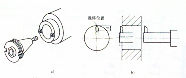
Spindle quasi stop is also called spindle orientation. The instruction code is M190 and the general spindle stop (M05) is different. When the spindle is stopped, the spindle must be stopped at the specified position, while the milling machine spindle motor has a torque to keep the spindle in a quasi-stop position and against the external load of the spindle. Spindle quasi-stop for the following occasions: the center of the machining center when the spindle orientation, so that the handle keyway into the spindle end key, as shown; fine boring retract the spindle when the first directional quasi-stop, the radial offset a short distance, and then axially retract the knife to avoid scratching the machined surface, as shown.
To achieve the milling machine spindle directional control, there must be a turn signal support. A turn signal is obtained according to the different spindle configuration has three ways: one is the spindle motor is installed with a rotary encoder signal; two is a rotating spindle encoder signal; three is the main external a turn signal (proximity switch).
2. Spindle positioning
In the full-function CNC milling machine, the spindle can be fixed angle positioning, such as 45°, 90°and 135°. Spindle positioning function with the power tool holder can be parts of the drilling and milling and other processing. When the workpiece cylindrical cylindrical cutting is completed, the tool holder from the drive head to the processing position. At the same time spindle positioning, drilling from the drive head.

2017年9月28日星期四

Milling machine spindle rigid tapping

Rigid tapping is also one of the important control modes of the milling machine spindle. In the tapping process, the spindle speed and the Z-axis feedrate fZ must be satisfied:
                    fZ = tap pitch x spindle speed
In the normal way to tapping processing, due to the spindle and Z axis feed acceleration and deceleration characteristics are inconsistent, tapping screw on the tap must be equipped with spring chuck, in order to compensate for the Z axis feed and spindle does not synchronize the pitch error. 
The handle with a spring chuck is shown in the figure. When the thread is tapped in this way, when the tap is rotated and the Z axis is stopped, the spindle does not stop immediately, the tapping spring chuck is compressed for a distance; when the tap is rotated in the reverse direction of the Z axis, the milling machine spindle accelerates, the spring chuck is stretched again. Common way to attack the thread cycle can only meet the general accuracy of the processing of screw holes. In addition, if the spindle speed is high when the thread is tapped, the telescopic range of the spring chuck must be large enough so that the spindle speed can only be limited to 600r/min or less when tapping the thread in this way.
Rigid tapping, also known as synchronous feed tapping. Rigid tapping does not require a spring chuck and a rigid taper shank as shown. Rigid tapping, the milling machine spindle speed and Z-axis feed speed to establish a synchronous relationship, so that the spindle speed and Z-axis feed speed to ensure a linear proportional relationship, as shown.
When the tapped thread is machined with a rigid tapping thread, the spindle rotates synchronously with the Z axis feed and decelerates simultaneously when the Z axis is tapped to the command position. The spindle reverse start acceleration is also synchronized with the Z axis reverse feed start acceleration. In addition, the rigid tapping in the tap strength allows the case, the milling machine spindle speed can be high, up to 4000r/min, processing efficiency significantly improved, and the thread accuracy is guaranteed.

2017年9月27日星期三

Siemens milling machine spindle motor and driver

Siemens milling machine spindle motor and driver are commonly used on machines. Let's get to know it today.
1. Siemens AC spindle motor
As shown in the figure for the Siemens 1PH7 AC spindle motor appearance and composition.
1PH7 AC milling machine spindle motor is a forced air-cooled asynchronous motor that is dissipated through a separately installed fan. The stator winding is embedded with a thermistor for detecting the temperature of the motor. The rotor shaft ends are connected to an encoder for detecting rotor speed and angular displacement. The encoder is connected to an external device via a cable plug or DRIVE- CLiQ interface, and the encoder can select an incremental encoder or an absolute encoder.
2. Siemens 611Ue driver
Siemens 611Ue driver is a DC common bus inverter, composed of power modules and power modules. 611Ue driver and Siemens SI-NUMERIK 802D CNC system supporting the use of milling machine spindle and servo drive. The appearance and composition of the 611Ue drive are shown in the figure.
The power module consists of rectifier module, filter capacitor and control circuit, etc., through the input of the three-phase AC rectifier, filtering, power module to provide DC bus voltage, while the power supply module also provides +5 V, +15 V and +24 V control power, through the equipment bus for the power supply module and power module internal control circuit. The control circuit, in addition to monitoring the DC bus, also performs temperature and operation monitoring, as well as enable control. There are two forms of power supply module, one is the uncontrolled power supply module (also known as feeding power module); Second, regenerative feedback power supply module (also known as feed / regenerative feedback power supply module).
The above is the basic introduction about Siemens milling machine spindle motor and driver.

2017年9月26日星期二

FANUC milling machine spindle motor

FANUC AC spindle motors have αi series and βi series. The former is a high-performance milling machine spindle motor, and αi series of drives supporting; the latter for the ordinary spindle motor, and βiSVSP series drive matching. FANUC AC milling machine spindle motor is a variable frequency dedicated motor. As shown in the figure is FANUC αi / βi AC spindle motor appearance and composition.
FANUC αi AC spindle motor stator no chassis, stator core shape was polygonal. The core of the edge of the axial ventilation holes, the motor has a separate power supply at the end of the cooling fan, the milling machine spindle motor forced cooling, the stator core in the air directly heat; rotor and ordinary three-phase AC motor, in addition, the stator winding is also equipped with thermistor. When the motor due to overload or winding short circuit caused by winding temperature rise to a certain value, the thermistor resistance changes. The temperature detection circuit in the spindle amplifier monitors the change of the resistance value and is fed back to the CNC system via the serial bus. The CNC system can stop the control signal of the spindle immediately after the judgment and processing, and issue the alarm that the milling machine spindle motor is overheating or overload.
FANUC αi spindle motor in the magnetic sensor for rotor speed and angular displacement measurement, a 128 pulse/turn, 256 pulse/turn, 512 pulse/turn three specifications, without zero position signal (also known as a turn signal) for the Mi series, with zero position signal for the MZi series.
The above is about FANUC milling machine spindle motor basic introduction, you are welcome to continue to focus on updates.

2017年9月25日星期一

CNC milling machine spindle motor (Part 2)

In the previous article we mainly introduced the composition of the CNC milling machine spindle motor, today we come to explore the operating principle of the spindle motor and frequency control mode.
1.Operating principle
CNC milling machine three-phase AC induction motor operating principle is shown in the figure.
Three-phase AC asynchronous motor stator winding into the three-phase AC generated after the rotating magnetic field, the speed no known as the synchronous speed. no = 60f/p, p for the stator winding pole pairs, f for the stator winding power supply frequency, change f to change no. The rotating magnetic field cuts the guide bar in the rotor core and generates an induced current in the guide bar. In this way, the rotor bar with induced current interacts with the rotating magnetic field to generate electromagnetic torque, and the rotor rotates with the rotating magnetic field at the rotational speed nM under the action of the electromagnetic torque. Because the motor running state when the rotor speed can only be less than the synchronous speed, so called asynchronous motor; and because the rotor bar in the current from the rotating magnetic induction, it is also known as induction motor. When the power frequency f decreases, the rotating magnetic field speed no decreases, but because of the rotor mechanical inertia, the rotor speed nM instantly remain unchanged, at this time, the rotor speed is greater than the rotating magnetic field speed, the motor is in the power brake state, the motor winding flows out.
2. Frequency control
Changing the power frequency of the milling machine spindle motor can realize the speed regulation of the motor. Three-phase AC induction motor frequency conversion speed is usually U/f and vector control. In order to meet the requirements of the three-phase AC asynchronous motor stator winding electromagnetic frequency requirements, in the rated frequency (50Hz) below the frequency control, change the frequency f at the same time also change the stator voltage U, and keep the voltage / frequency is not change. In this speed range, the maximum electromagnetic torque remains constant and constant torque is achieved. Rated frequency above the frequency control, the stator winding voltage U to maintain the rated voltage (380V) unchanged. In this speed range, the electromagnetic torque decreases with the frequency rise, and the electromagnetic power unchanged, to achieve constant power speed, as shown.
The above is a brief introduction about the CNC milling machine spindle motor operation principle and frequency control mode. 

2017年9月24日星期日

CNC milling machine spindle motor (Part 1)

CNC milling machine spindle is driven by the spindle motor. CNC system through the control of the spindle motor to achieve the control of the spindle. At present, CNC milling machine spindle motor commonly used three-phase AC asynchronous motor and variable frequency drive.
Spindle motor drive has two configurations: First, the ordinary three-phase AC asynchronous motor and inverter; Second, the CNC system supporting the spindle motor and spindle drive. The former is often used in ordinary CNC milling machine, to achieve frequency control, positive, reverse start and stop and other basic control; the latter for multi-function CNC milling machine, in addition to the basic control of the spindle, but also to achieve orientation, positioning and spindle servo control.
Ordinary three-phase AC induction motor is consist of stator and rotor, as shown.
The stator includes a base, stator core and stator three-phase windings. The stator core is made of silicon steel sheet, and the inner circumference is covered with a coil groove. The coil groove is fitted with three symmetrical windings. The winding terminal is introduced into the junction box on the base frame and can be connected into a triangular winding or star winding. Made of silicon steel sheet stacked, the outer circumference are covered with a coil groove, coil groove cast with aluminum guide bar.
Ordinary asynchronous motor rotor is also installed on the cooling fan, when the ordinary three-phase AC asynchronous motor with the inverter speed, and the rotor speed is low, the cooling fan air volume is not enough to cool the motor, the motor easy to heat, serious will damage the stator winding insulation, resulting in short circuit. In order to meet the needs of frequency control, the development of a special frequency asynchronous motor, as shown. Frequency conversion special asynchronous motor has a special cooling fan motor, the motor body for forced cooling, fan motor power supply alone, the fan air flow and the motor speed has nothing to do. In addition, the frequency conversion asynchronous motor also improves the insulation performance of the stator winding, some frequency conversion special asynchronous motor stator winding is also embedded in the thermistor, for the motor temperature detection.
The above is the introduction about CNC milling machine spindle motor structure, welcome you continue to pay attention to the updated content.

2017年9月22日星期五

CNC milling machine tool changer manipulator

For the use of disc magazine CNC milling machine, tool changer manipulator is essential. Cam-type tool changer manipulator and spindle with the ability to continuously achieve grasping knife, knife exchange and insert the action, the structure shown in figure.
1) Grasping the knife. The manipulator starts the motor for the first time. The motor drives the end cam and the cylindrical cam through the bevel gear. The cylindrical cam drives the cam roller to rotate the spline shaft. The spline sleeve drives the mechanical shaft by rotating it in the counterclockwise direction 65° or 75°, the manipulator grasping knife action. When the manipulator handle the knife in place switch is turned on, the robot electric brake immediately stops, completes the manipulator grasping knife control. During this time, the manipulator does not move axially.
2) Milling machine spindle loose knife mechanism action. The claws release the milling machine spindle handle, and issued the spindle release in place signal.
3) The second start of the manipulator motor, through the bevel gears simultaneously drive the end of the cam and cylindrical cam rotation, the mechanical hand shaft order to complete the knife, exchange and insertion of three movements: ①the end of the cam control rocker swing, so that the movement of the shaft , To achieve a knife action. During this time, the cam roller does not rotate, so the manipulator does not rotate. ②the end of the knife, the cylindrical cam through the cam roller to drive the spline shaft rotation, and then by the spline shaft drive the manipulator shaft rotation 180°, to achieve tool exchange action. During this period, the rocker arm does not swing, the manipulator does not move axially. ③the end of the cam again control the rocker swing, so that the movement of the robot shaft to achieve the knife action. During this time, the cam roller does not rotate, so the manipulator does not rotate. When the knife in place switch is turned on again, the manipulator brake immediately stops.
4) Milling machine spindle loose knife mechanism action, the claw clamping spindle in the handle, and issued a spindle clamping in place signal.
5) The third time the manipulator is started, the cylindrical cam drives the cam roll to rotate the spline shaft. The spline sleeve drives the mechanical hand shaft to rotate 65°or 75°clockwise to achieve the reset action. When the manipulator returns to its original position, the home switch is turned on and the manipulator's motor stops immediately.
The above is the work of CNC milling machine tool change manipulator. Tool changer through the cam and other mechanical transmission mechanism, with the manipulator motor 3 times start and stop, to achieve the original position → grasping knife → knife (spindle loose knife) → exchange → plug (spindle cutter) → reset the action process.

2017年9月21日星期四

CNC milling machine disc tool magazine

The disc tool magazine is also a magazine that is often used in CNC milling machine
Disc tool magazine tool change process by the knife chopper, knife sets flip, tool changer and spindle and other action linkage to achieve. The entire tool change process by the CNC system control PLC. The disc magazine tool change is a random tool change, that is, after each tool change, the tool number and tool holder number is not necessarily the same. During the tool change, the robot can simultaneously grasp the knife from the magazine and the spindle, the knife and the knife, the tooling efficiency is high.
The disc magazine consists of cutter head motor, rotary cutter, indexing mechanism, knife cover and inverting mechanism. The cutter head motor drives the rotary cutter through the indexing mechanism. The cutter cover is fixed on the rotary cutter by the bracket, Rotate with the cutter head.
1. Select knife
When the T command is executed, the system first determines whether the tool is in the magazine. If not, the system will issue a T code error alarm. In addition, but also to determine whether the selected tool on the spindle, if already on the spindle, then complete the tool change control. And then determine the specific position of the selected tool in the magazine, if the selected tool is in the current tool change position, the turntable motor does not act, waiting for the robot to exchange the tool.
If the selected tool is not in the tool change position, the system determines the shortest path and the number of steps of the current position of the selected tool to the tool change position. The output control signal causes the turntable motor to turn forward or reverse, The count switch on the turntable moves once. When the selected tool to the tool change position, the turntable motor brake stopped to complete the T code of the knife control.
2. Knife sets flip
Since the tool axis in the magazine is perpendicular to the tool axis in the milling machine spindle, the tool holder is turned 90°downward before the tool change so that the tool axis in the tool holder is parallel to the axis of the spindle. After the tool change, turn the tool cover upside down 90°.
When the tool set of the selected tool is turned to the tool change position, the roller in the rear of the tool holder enters the fork, the front chamber of the cylinder is fed, the piston is moved up and the fork is driven to turn the tool cover 90°, knife cover down flip detection switch signal. When the cylinder is in the back chamber, the piston moves down and drives the fork to turn the tool cover up 90°, and the tool set reset detection signal is signaled.
The above is the composition of the CNC milling machine disc tool magazine and the process of change tool introduction.

2017年9月20日星期三

CNC milling machine bamboo hat type tool magazine (Part2)

Today, let us talk about the tool change process of the CNC milling machine bamboo hat type tool magazine.
The bamboo hat type tool change is an absolute tool change, that is, after each tool change, the tool number and tool holder number is one-to-one correspondence.
Bamboo hat type tool magazine without the need to manipulate the tool, through the spindle box and spindle mechanism to achieve the linkage, the tool change process:
1) CNC system to get the tool change instructions, the spindle automatically return to the tool change point, while the spindle to achieve quasi-stop control.
2) The milling machine cutter rotates to the tool change point corresponding to the tool number (set to the old tool) on the current spindle.
3) The cutter head from the original position by the cylinder piston, when the clip to grasp the old tool on the spindle, the knife in place switch switch, said the grasping knife to complete.
4) Spindle knife action, the old knife loose, and the spindle cone hole blowing, when the spindle loose knife in place switch, said the loose knife to complete.
5) The milling machine spindle is moved up and the old tool on the spindle remains on the tool holder and the knife is finished.
6) The magazine rotates again, and the tool holder (set to the new tool) corresponds to the tool holder number to the tool change point.
7) The spindle is moved down again to the tool change point, the new tool is inserted into the spindle taper hole, and the tool change is completed.
8) Spindle knife action, the new tool in the spindle in the knife, when the spindle cutter in place switch, said the tight knife to complete.
9) Cutter cylinder cylinder retraction, when the knife reset switch is turned on, the tool change process is over.
The above is the tool change process introduction of the CNC milling machine bamboo hat type tool magazine, the next article we will introduce other types of tool magazines.

2017年9月19日星期二

CNC milling machine bamboo hat type tool magazine (Part1)

There are a variety of CNC milling machine tool magazines. We first take a look at the bamboo hat type tool magazine.
The bamboo hat type tool magazine is mainly used for vertical machining center automatic tool change, installed in the milling machine column, the structure shown in figure.
The cutter head is equipped with a clip, each clip corresponds to a tool holder number, used to hold the handle, the tool number corresponds to the tool holder number. The entire cutter head is suspended from the two cylindrical rails on the magazine holder through the sleeve. The cylinder holder is fitted with a cylinder, the cylinder piston is connected to the cutter head, and the piston is extended or retracted. The limit of the extension or retraction of the cutter head is extended by the magnetic switch installed on the cylinder (some tool magazines are fitted with a stroke switch or a proximity switch on the bracket).
The upper part of the cutter head is equipped with an indexing sheave, and the cutter head motor drives the cam to rotate, and the roller is rotated around the motor axis. The roller cooperates with the indexing sheave. When the cam is rotated for one week, The disk turns through a knife seat, and the counting switch is turned off once. The milling machine CNC system PLC counts the input count switch signal and is controlled by the PLC to judge whether the tool holder corresponding to the tool has been transferred to the tool change position.
The above is the structure introduction of the CNC milling machine bamboo hat type tool magazine.

2017年9月18日星期一

CNC milling machine spindle drive mode

The spindle drive modes of CNC milling machine are belt drive and gear shift drive in two ways. Now let's look at these two ways separately.
1.Belt drive
In the case of the spindle motor with a special three-phase AC asynchronous motor and a variable frequency speed control, since the spindle motor has a wide range of constant torque and constant power speed range, the spindle motor can be connected to the milling machine spindle through the drive belt. Spindle motor control to achieve the spindle speed and steering control, simplifying the spindle drive mechanism. The belt drive is used for spindle milling of CNC milling machines and medium and small machining centers.
2.Gear shift drive
In the case of spindle motor with ordinary three-phase AC asynchronous motor and frequency control, in order to obtain the spindle low speed and increase the constant power speed range, some CNC milling machine spindle gear shift.
Gear shift mechanism with hydraulic fork and electromagnetic clutch in two forms, as shown in the figure, the gear shift using hydraulic cylinder and fork for high and low two switch. When the high-speed gear, the solenoid valve action, the hydraulic cylinder piston out, through the fork to slip gear shift, Z1 and Z2 meshing, Z3 and Z4 off, high-speed detection device in place SQ1 signal, drive path: spindle motor → drive belt d1 / d2 → I axis → Z1 / Z2 → spindle. In the low gear, the solenoid valve moves, the hydraulic cylinder piston retracts, moves the slip gear by the fork, Z3 and Z4 are engaged, Z1 and Z2 are disengaged, the low gear detection switch SQ2 sends the signal, the transmission path: the spindle motor → drive belt d1 / d2 → I axis → Z3 / Z4 → spindle.
Gear shift has manual and automatic (M command) two kinds of operation.  Electromagnetic reversing valve movement and the shift position detection are controlled by the PLC of the CNC system.
The above is about CNC milling machine two kinds of spindle drive mode introduction, welcome you continue to pay attention.

2017年9月15日星期五

CNC milling machine basic control

Although CNC milling machine has many different types and the control is simple and complex, the basic control of CNC milling machine includes spindle control, feed control and auxiliary function control.
1. Spindle control
The basic functions of spindle control include spindle reversing and spindle speed control. Control of the spindle, in fact, the spindle motor control, that is, the spindle motor forward and reverse determines the steering of the spindle; spindle motor speed determines the spindle speed. The drive of the spindle motor is realized by the spindle drive. The basic requirement for spindle control is to keep the spindle speed stable. For this reason, an encoder is provided on the spindle motor or spindle for speed detection and feedback.
In order to ensure the accuracy of position control, usually in the spindle to install the encoder for spindle position detection and feedback. With the development of technology, some milling machines use electric spindle technology.
2. Feed control
Feed control includes point control and trajectory control, as shown.
(1) point control
Machining center drilling, reaming, reaming, tapping and boring are all point control. In the point control, the tool is not cut during the rapid movement from the current position to the next position. The movement path can be set artificially, but the position accuracy between the point and the point is guaranteed.
(2) trajectory control
CNC milling machine for contour processing are trajectory control. Trajectory control, the tool according to the provisions of the path cutting the workpiece, it is necessary to ensure the accuracy of the location, but also to ensure the stability of the tool movement speed.
The control target of the feed movement is the position control and the speed control, and the accuracy of the position control, the stability of the feed speed and the fastness of the command response are ensured. To achieve this goal, the CNC milling machine has a feed motion control for position detection and speed detection, such as gratings and encoders. With the development of technology, some CNC milling machine adopts linear motor drive, eliminating the ball screw, shortening the feed mechanical transmission chain, improve the mechanical transmission stiffness and accuracy, and the rapid response speed of the servo system.
3. Auxiliary function control
The auxiliary function is controlled by the M command and the T command through PLC control of the CNC system. It involves milling machine side input and output switch, such as button, key switch, proximity switch, proximity switch, relay, contactor and solenoid valve, and PLC ladder diagram. Among them, the spindle is reversing and stopping, lubrication and cooling are all CNC milling machine with auxiliary functions, the other also includes the knife knife selection, machining center tool change, machining center spindle tensioner, and rotary table and tray exchange, etc.

2017年9月14日星期四

CNC milling machine basic composition

Today we are going to talk about the basic composition of CNC milling machine and machining center. Come on and pay attention.
1. CNC milling machine
CNC milling machine according to function is divided into ordinary type and full function type.
(1) Main movement
The main movement of the mechanical transmission device, including the spindle, belt, spindle box ; spindle electrical drive devices, including spindle motors and spindle drives. CNC system on the input instruction data processing, the output control signal to the spindle drive, the spindle driver that the spindle motor to start, stop and frequency control and other control. In the multi-function CNC milling machine, the spindle in addition to speed control, there are spindle orientation, positioning and other control.
(2) Feed movement
The feed motor drives include X-axis and Z-axis ball screw pairs, rails, skids, etc. The feed electrical drive includes the X and Z axis servomotors and servo drives. The numerical control system carries on the data processing to the input instruction, outputs the control signal to the servo drive, the servo drive drives the servo motor to drive the ball screw, causes the slide to realize the feeding motion along the X axis and the Z axis, and finally makes the tool relative to the workpiece according to the processing program the specified movement trajectory and velocity movement.
(3) Auxiliary function
CNC milling machine basic auxiliary functions include cutting fluid switch control, lubrication control, tool change tool control, and the spindle box gear shift control. For multi-function CNC milling machine, auxiliary functions include hydraulic tailstock control and hydraulic chuck control. Auxiliary functions from the CNC system PLC and electrical control cabinet in the I / O modules, relays, contactors, and milling machine on the side of the various types of detection switches and gas hydraulic solenoid valve, according to the control logic to complete.
2. Machining Center
The spindle unit is installed in the main shaft box and is driven by the spindle motor through the transmission belt. The spindle drive receives the control signal from the numerical control system, drives the spindle motor to realize the frequency conversion speed control, and starts, stops and quasi-stop.
Before and after the exercise and the spindle box of X axis, Y axis and Z axis ball screw servo motor to achieve the milling machine table about sports, saddle up and down movement of the control signal; receiving a servo drive CNC system, drive X axis, Y axis and Z axis servo motor.
Besides the lubrication, cooling and other basic auxiliary functions, the machining center also has two important auxiliary functions: one is the loose and tight knife control in the spindle; the other is the cutter selection of the tool stock and the mechanical tool change control for the knife.

2017年9月13日星期三

CNC milling machine features

CNC milling machine is a typical product of mechanical and electrical integration. It is a computer as the control core, set milling machine, motor and drag, power electronics, sensors, automation, machine tools and PLC, and gas and hydraulic technology as one of the automated metal cutting equipment. The CNC system (Computer Numerical Control, referred to as CNC) is the core of control, is generally a dedicated computer. Compared to the ordinary milling machine, CNC milling machine processing parts are automatically carried out according to the processing program. The machining process is shown in the figure.
The programmer prepares the machining process (machine selection, tool selection, fixture selection, cutting quantity determination, etc.) according to the part drawing.
The operator will enter the processing program into the CNC system, after the workpiece clamping, tool adjustment and knife operation, the implementation of processing procedures.
CNC system on the processing program for data processing, the output control signal control machine parts of the action, automatic cutting, such as spindle start, stop and spindle speed conversion, tool relative to the workpiece feed track adjustment, automatic tool change, cutting fluid open, off and so on.
The basic features of CNC milling machine are:
1) There is no need to intervene too much in the process of machining, and the effect of machining accuracy is reduced to the minimum.
2) CNC milling machine itself mechanical precision and control accuracy are higher, every step in the processing process strictly in accordance with the processing procedures to ensure the accuracy of parts processing and consistency of accuracy.
3) CNC milling machine has high degree of automation, such as automatic tool change, automatic tool setting, etc., effectively shorten the non cutting time, high processing efficiency.
4) After adopting standardized and modularized cutters and clamps, different parts can be machined only by changing the corresponding processing program, and the adaptability is strong.